top of page

DATE:
INSTITUTE:
COURSE:
SKILLS:
Fall 2025
Duke University Pratt School of Engineering
Experimental Design & Research Methods (Team Project)
• Mechanical Design (Robotics)
• 3D CAD Modeling (SolidWorks)
• 3D Printing
This exploratory project introduces hydra, a slinky-inspired tendon-driven continuum robot (TDCR). Built from modular units that bend and flex through tendon actuation, the robot produces wave-like motion for locomotion. By applying tendon actuation to achieve slinky-like movement, hydra demonstrates a novel approach to mobile continuum robotics. This platform provides opportunities to investigate new forms of distributed actuation and bio-inspired locomotion, with potential applications in search-and-rescue, confined-space inspection, and soft robotics research.

-
Demonstrate feasibility of tendon-driven, slinky-like locomotion as a novel approach to continuum robot movement
-
Introduce efficient and scalable locomotion capabilities while preserving adaptability and dexterity of traditional tendon-driven continuum robots
-
Create platform that provides opportunities to investigate new forms of bio-inspired locomotion and robotics research
Goals
Features
-
Modular mechanical design of 3D-printed components, with reconfigurable length, pre-programmable compliance, and wave-based locomotion
-
Compliant backbone structure containing tendon/wire routing
-
Embedded electronics housing, enabling untethered mobility
-
Teleoperation via antagonistic tendon actuation
HYDRA MECHANICAL DESIGN
-
Robot architecture is composed of 3D-printed modular units with integrated electronics housing
-
Robot body is made up of spacer discs, connectors, and support wings that align and constrain the tendon routing while maintaining structural flexibility
-
All components are modeled in SolidWorks and manufactured using 3D-printed parts
-
Module unit design is adapted from a research paper by the Continuum Robotics Laboratory at University of Toronto
Module Unit Assembly
Each module unit assembly consists of two spacer discs, two connectors, and four support wings. These assemblies form the individual bending segments of the robot's structure.
3D Animation in SolidWorks
End Effectors
The end effectors serve a dual purpose: they act as the robot's "feet" for locomotion and contain the electronics. They are divided into three stacked layers, each connected using counterbored fasteners.

3D Animation in SolidWorks
Electronics Housing
The internal structure of the end effectors serves as the housing for all electronic components. We mounted each component to its designated layer with snug fits and screws to keep everything firmly in place during motion and transportation.

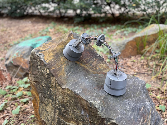
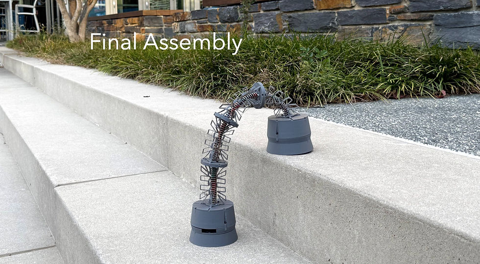
Full Robot Assembly
Using four connected module units, two end effectors, and a compression spring as the backbone, our full robot assembly is shown below.

bottom of page